ESTCube-1
 Mission
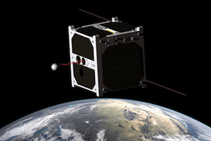
ESTCube-1 is the first Estonian satellite and it is being built in Estonia by students from Tartu University, Estonian Aviation Academy, Tallinn University of Technology and University of Life Sciences. The project started in 2008 and is currently being assembled and tested. The satellite will be launched in April 2013. The satellite’s payload has been developed in conjunction with Finnish Meteorological Institute and German Space Center (DLR).
The main mission of the satellite is to test the electric solar wind sail, a novel space propulsion technology that could revolutionalize transportation within the solar system. As Estonia’s first satellite, the project will also be used to build Estonian infrastructure for future space projects and to educate space engineers.
The electric solar wind sail (http://electric-sailing.fi/) is a novel method of propulsion within the Solar system using the flow of electrically charged particles emanating from the Sun, or the solar wind. The system was invented in Finland by Pekka Janhunen and ESTCube-1 is its first orbital proof-of-concept test.
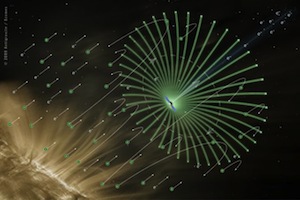 The technology is based on the electrostatic interaction between the electric field generated by the satellite and the high-speed particles being ejected from the Sun. The spacecraft utilizing this method would first deploy a set of electrically charged wires, which allow to generate an electric field over a large area. This area effectively forms a “sail” that can be pushed by the charged particles by being diverted by it and therefore transferring momentum to the craft. A 1000 kg satellite would contain a 100 kg electric sail module that could deploy 100 tethers, each with the length of 20 km. Overall this would result in a net thrust of 1 N. This force might seem small, but this can be applied to the satellite over its entire lifetime using only the energy generated by satellite’s solar arrays. During one year this could increase the velocity of the craft by 30 km/s.
The technology would make it possible to travel in the Solar system cheaply and fast, allowing asteroid mining, landing missions to Mercury and transferring data by “data clippers”.
Mission Phases
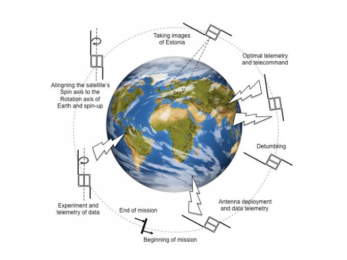
- Carrier rocket takes the satellite into orbit and deploys it.
- 5 minutes after deployment the satellite starts up and starts preliminary system checks to determine the integrity of the satellite’s hardware.
- 30 minutes after deployment the radio antennas of the satellite will be deployed and communications with the Earth will be made possible.
- 40 minutes after deployment the satellite’s radio beacon will bea activated and first messages will be sent back to the Earth (this is the first time the satellite’s successful launch can be determined)
- Satellite’s beacon will be held active for a couple of days to determine satellite’s health
- The satellite will turn on all of its subsystems and will stay in standby for commands from the groundstation.
- The groundstation will communicate with the satellite for diagnostics and possible software updates
- Satellite’s rotation will be stabilized and first camera pictures will be taken.
- The main mission will start: the coils within the satellite will be used to spin it up and the tether deployment starts.
- Tether deployment ends, the tether will be electrified and measurements will start. The satellite will keep sending telemetry for confirming the E-sail effect.
Orbital parameters
Name                 ESTCube-1
NORAD                39161
COSPAR designation   2013-021-C
Inclination (degree) 98.127
RAAN                 270.338
Eccentricity         0.0010865
ARGP                 41.580
Orbit per day        14.69011480
Period               1h 38m 01s (98.2min)
Semi-major axis      7 042 km
Perigee x apogee     657 x 672 km
Drag factor          0.000135300 1/ER
Mean Anomaly         318.623
Downlink
437.250 MHz – CW beacon, call sign ES5E/S
437.505 MHz – 9600 bps AX.25 telemetry, call sign ES5E-11
Preliminary TLE
ESTCube-1
1 00000U 00000    13127.17171296  .00000000  00000-0  10000-3 0 00005
2 00000 098.1390 205.7730 0134000 220.5400 211.2631 14.71982716000009
Telemetry
Beacon mode ID is a character:
“E” – Normal mode beacon
“T” – Safe mode beacon
Normal mode beacon ends with character “K”
Safe mode beacon ends with characters “KN”
Correct beacon lengths are:
Normal mode – 43 characters
Safe mode – 52 characters
HEX to Morse symbol (CW) coding
| Hex | 0 | 1 | 2 | 3 | 4 | 5 | 6 | 7 | 8 | 9 | A | B | C | D | E | F |
| CW | T | W | U | S | H | 5 | 6 | M | Z | N | A | B | C | D | E | F |
When sending beacon data, please replace lost symbols with character “#”. Feel free to use space characters convenience when entering the beacon string.
For a valid beacon either must be existing:
- Beacon mode ID character (in the beginning)
- Beacon end character
If the time moment of beacon start or end is recorded, then even a partial beacon info is useful. Partial info should contain either beginning or end of the beacon message.
Normal mode beacon
ES5E/S E AAAAAAA BBCCDD EEFF GGG HIIJJ KKLLMM NNOO K

AAAAAAA      EPS timestamp 28 lowest bit UNIX timestamp      [DD.MM.YYYY HH:MM:SS]
BB     Main bus voltage           N (uint 8)                 [V]
CC     Average power balance      N (signed int 8)           [W]
DD     Battery A voltage          N (uint 8)                 [V]
EE     Battery B voltage          N (uint 8)                 [V]
FF     Battery A temperature      N (uint 8)                 [V]
GGG    Spin rate Z                (N*720)/2047 (signed int 12)      [deg/s]
H      Received signal strength   N (signed int 4)           [dBm]
II     Satellite mission phase    bit 6-7N (uint 2)   [0="Detumbling", 1="Nadir pointing", 2="Tether deployment", 3="E-sail force measurement"]
Time since last reset:     CDHS   bit 4-5      N (uint 2)          [Hours]
                           COM    bit 2-3      N (uint 2)          [Hours]
                           EPS    bit 0-1      N (uint 2)          [Hours]
JJ     Tether current             N*5/255 (uint 8)           [mA]
KK     Time since last error:ADCS bit 6-7      N (uint 2)          [Hours]
                           CDHS   bit 4-5      N (uint 2)          [Hours]
                           COM    bit 2-3      N (uint 2)          [Hours]
                           EPS    bit 0-1      N (uint 2)          [Hours]
LL     CDHS System status  bit 2-7      Last error (uint 6)[Error code number]
                                  bit 0-1 Parameter (uint 2) [Raw value]
MM     EPS System status          N      Last error (uint 8)       [Error code number]
NN     ADCS System status         bit 2-7 Last error (uint 6)       [Error code number]
                                  bit 0-1 Parameter (uint 2) [Raw value]
OO     COM System status          bit 2-7 Last error (uint 6)       [Error code number]
                                  bit 0-1 Parameter (uint 2) [Raw value]
Safe mode beacon
ES5E/S T AAAAAAA BBCCDD EEEE FFGGHH IIJJKK LLMMNN OPQQ RRSS KN

AAAAAAA      EPS timestamp        28 lowest bit UNIX timestamp      [DD.MM.YYYY HH:MM:SS]
BB     Error code 1               N (uint 8)                 [Error code number]
CC     Error code 2               N (uint 8)                 [Error code number]
DD     Error code 3               N (uint 8)                 [Error code number]
EEEE   Time in safe mode          N (uint 16)                [Minutes]
FF     Main bus voltage           N (uint 8)                [V]
GG     Status 1                   bit 7  CDHS A state        [0=OK, 1=FAULT]
                                  bit 6  CDHS B state        [0=OK, 1=FAULT]
                                  bit 5  CDHS BSW state             [0=OK, 1=FAULT]
                                  bit 4  COM 3V3 state       [0=OK, 1=FAULT] // also defines the condition of uplink
                                  bit 3  PL 3V3 state        [0=OK, 1=FAULT]
                                  bit 2  PL 5V state         [0=OK, 1=FAULT]
                                  bit 1  CAM state           [0=OK, 1=FAULT]
                                  bit 0  ADCS state          [0=OK, 1=FAULT]
HH     Status 2                   bit 7  Battery A charging  [0=OK, 1=FAULT]
                                  bit 6  Battery A discharging      [0=OK, 1=FAULT]
                                  bit 5  Battery B charging  [0=OK, 1=FAULT]
                                  bit 4  Battery B discharging      [0=OK, 1=FAULT]
                                  bit 3  TBD                 [0=?, 1=?]
                                  bit 2  TBD                 [0=?, 1=?]
                                  bit 1  TBD                 [0=?, 1=?]
                                  bit 0  TBD                 [0=?, 1=?]
II     Status 3                   bit 7  SPB A regulator     [0=OK, 1=FAULT]
                                  bit 6  SPB B regulator     [0=OK, 1=FAULT]
                                  bit 5  3V3 A regulator     [0=OK, 1=FAULT]
                                  bit 4  3V3 B regulator     [0=OK, 1=FAULT]
                                  bit 3  5V A regulator             [0=OK, 1=FAULT]
                                  bit 2  5V B regulator             [0=OK, 1=FAULT]
                                  bit 1  12V A regulator     [0=OK, 1=FAULT]
                                  bit 0  12V B regulator     [0=OK, 1=FAULT]
JJ     Battery A voltage          N (uint 8)                 [V]
KK     Battery B voltage          N (uint 8)                 [V]
LL     Battery A temperature      N (uint 8)                 [V]
MM     Battery B temperature      N (uint 8)                 [V]
NN     Power balance              N (signed int 8)           [W]
O      Firmware version           N (uint 4)                 [Version number]
P      Crash counter              N (uint 4)                 [Number of crashes]
QQ     Forwarded RF power         N (signed int 8)           [dBm]
RR     Reflected RF power         N (signed int 8)           [dBm]
SS     Received signal strength   N (signed int 8)           [dBm]
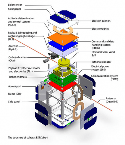
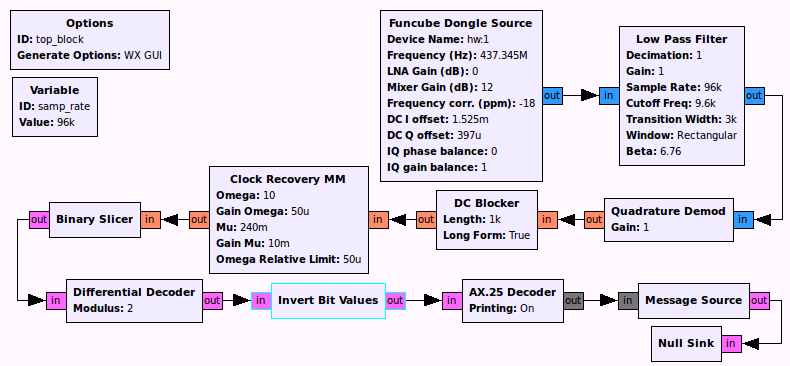
ESTcube-1 GNU Radio receiver:
Follow the link and download the gr-ec source and compile it as mentioned on the page. After that create the following GNU radio blocks to decode the data from ESTCube-1. This setup can also be used by other AX25 signals.
Status
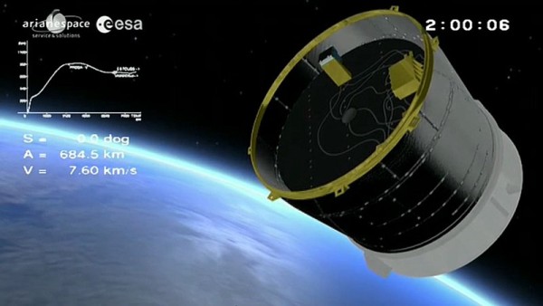
Will be launched with a Vega rocket from Kourou French Guiana. Liftoff is scheduled on May 4 at 02:06:31 UTC, separation at 04:07:17 UTC. Beacon should activate 40 minutes after separation. Launched from Kourou in the Caribbean on May 7, 2013 at 0206 UTC on an ESA Vega rocket into a 704 km orbit and Active
Homepage and other references:
ESTCube website
Solar-propulsion see www.electric-sailing.fi.
