Kenwood TS-711 – TS-811
CTCSS Modification for the TS-711e and TS-811e
Original information can be found via the following link. This is the website from PA3CSX.
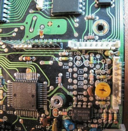
| Modification of Control Unit (X53-1410-XX) to accomodate TU-5 board | Remove the Tone Unit X52-1290-60 (1750 Hz). Disconnect alle the connectors of the Control Unit. Remove the 2 screws on the side which locks the coolingplate to the chassis. Remove all screws which holds the Control Unit. Open up the 6 solderholes and place a 6 pen header with sufficient pinlength. Solder and cut header to correct length. Remove R55 22 kOhm (near J9) Place jumper W2 (near J9, crossing one side of the removed R55 connecting J9-1 and TU-5 pen TH) Place C56 470 pF axiaal ceramic capacitor (near J9, between J9-1 and ground) Remove D30, D33 and D34 (near J1) Remove D16 (near TU-5 unit) |
 |
|
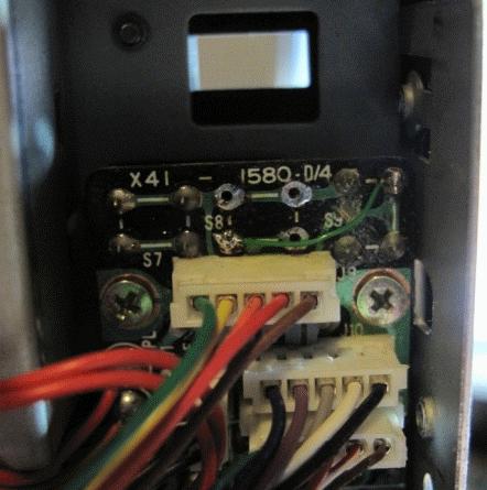
| Alter Power Switch Unit | Remove on/off switch make a cut in the circuittrace of S9 (on the rightside of the text ‘S9’) Place a jumper wire from the middle switch S8 left-under to the right switch S9 right upper side as done with the green wire. |
 |
|
| By wiring the TONE switch to the absent middle switch access to the CTCSS menu is obtained. | |
 |
|
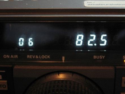
| Activate the changes made to the diode matrix. | Reset the radio. Hold the A=B button and power on the TS711. Then release the A=B button. New RX range 144 – 153 MHz and new TX range 144 – 146 MHz When the OFFSET button is used, pin 3 (TH) the TU-5 unit is active (5 Volt) and CTCSS is transmitted during TX. |
| Adjustment of CTCSS modulation | Adjust for a deviation between 500 and 750 Hz |
| Used materials: | 1 x header 6 pens 1 x capacitor 470 pF ceramic axial 1 x tu-5 unit from www.piexx.com |
