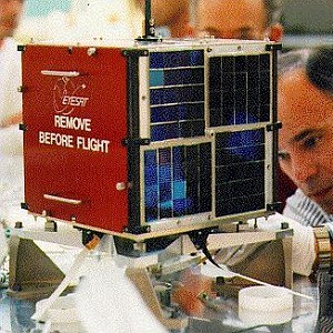
AMRAD OSCAR (AO-27)
 AO-27 is an amateur satellite constructed by the Amateur Radio Research and Development Corporation (AMRAD) at the facilities of Interferometrics in McLean, Virginia.
It was originally designed as a commercial satellite known as EYESAT-1 but its completion was halted part way through the project. An agreement was made for AMRAD to finish the construction of the satellite and add an amateur satellite transponder. AO-27 is an “FM Repeater” in space. It essentially consists of a crystal controlled FM receiver operation at 145.850 MHz and a crystal controlled FM transmitter operating at approximately 436.795 MHz. Output power of the transmitter can be set to over 1 watt (rarely used), 0.5 watts (normal operation), or under 0.1 watts (exciter only). The uplink antenna is the linear polarized whip on the top face of the spacecraft and is shared with the commercial payload’s receivers. The downlink antenna is a 1/4 wave whip mounted on the bottom face of the spacecraft. Polarization is nominally linear, the rotation and revolution of the spacecraft and propagation effects will cause the actual signal polarization at a ground station to vary widely during a pass.
Orbital parameters
Name                 AO-27
NORAD                22825
COSPAR designation   1993-061-C
Inclination (degree) 98.251
RAAN                 190.750
Eccentricity         0.0008681
ARGP                 171.364
Orbit per day        14.29136207
Period               1h 40m 45s (100.75 Min)
Semi-major axis      7173 km
Perigee x apogee     788 x 801 km
Drag factor          -0.000009537 1/ER
Mean Anomaly         188.766
Downlink
436.795 MHz (FM)
Uplink
145.850 MHz (FM)
Mode and Antenna Polarization:
V: Linear
U: Linear
Telemetry
Decoding is possible with a 1200 bps AFSK (packet) modem in kiss mode. The kiss output can be used as input to for example the AMRAD AO-27 decoder from DK3WN.
The channels 1 thru 15 are from the receiver. The AART board in
the receiver has a problem that it will latch the lines on the bus so
the RX telemetry was disabled right before launch.

Parameter = A*n² + B*n + C

Ch    name                 C              B           A       unit
-------------------------------------------------------------------

16    Battery 0     :   +1.900       -0.0041666   0           Volts
17    Battery 4     :   +1.900       -0.0041666   0           Volts
18    Battery 2     :   +1.900       -0.0041666   0           Volts
19    Battery 6     :   +1.900       -0.0041666   0           Volts
1A    Battery 1     :   +1.900       -0.0041666   0           Volts
1B    Battery 5     :   +1.900       -0.0041666   0           Volts
1C    Battery 3     :   +1.900       -0.0041666   0           Volts
1D    Battery 7     :   +1.900       -0.0041666   0           Volts
1E    Solar Array   :   +7.9650682   +0.0686763   0           Volts
1F    8 V Bus       :   +7.0473333   +0.0113333   0           Volts
20    5 V Bus       :   +3.7500000   +0.0125000   0           Volts
21    10 V Bus      :   +8.1699655   +0.0204189   0           Volts
22    Battery #5    :   +145.08000   -0.9200000   0           deg C
23    10 V Bus Cur  :   -8.5766634   +4.6595804  +0.0090934   mAmps
24    8 V BUS  Cur  :   -0.2637419   +1.9861031  -0.0002043   mAmps
25    5 V BUS Cur   :   -1.6011952   +5.3687733  -0.0001976   mAmps
26    -X Array Cur  :   +2.5393978   +1.2945522   0.0029869   mAmps
27    +X Array Cur  :   +3.8778891   +1.2337216   0.0034585   mAmps
28    -Y Array Cur  :   +1.9453662   +1.2869215   0.0036150   mAmps
29    +Y Array Cur  :   +0.8377529   +1.3201728   0.0030064   mAmps
2A    -Z Array Cur  :   -5.1705101   +1.3962301   0.0002714   mAmps
2B    +Z Array Cur  :   +3.7194087   +1.1232609   0.0041865   mAmps
2C    External Cur  :   -1.3147137   +1.5779074   0.0013702   mAmps
2D    BCR Input Cur :   +9.8611991   +1.0931975   0.0099122   mAmps
2E    BCR Output Cur:   0            +1.000       0           Count
2F    BCR Plate Temp:   +145.08000   -0.9200000   0           deg C
30    BCR PC-Board  :   +145.08000   -0.9200000   0           deg C
31    Battery #0    :   +145.08000   -0.9200000   0           deg C
32    TX-A RF OUT   :   -21.995773   -8.1787836  +0.2143451   mWatts
33    TX-B RF OUT   :   -111.61003   -5.2876206  +0.2271923   mWatts
34    TX THER A     :   +140.69230   -0.8846154   0.000       deg C
35    TX THER B     :   +140.69230   -0.8846154   0.000       deg C
36    TX THER C     :   +140.69230   -0.8846154   0.000       deg C
37    TX THER D     :   +140.69230   -0.8846154   0.000       deg C

50    EDAC Counter  :   0             1           0           Count
51    Eclipse       :   0             1           0           Count
52    Set Point     :   0             1           0           Count
53    Tepr State    :   0             1           0           Count

FF    VERSION       :   4.0           0           0           Version
Status
Inactive, FM repeater – Telemetry transfer over Italy. Don’t transmit unless you hear the FM repeater functioning.
Update information: October 18th, 2012 We tried to do a restart of the high level code today which did not work out. We left the transmitter on to drain the batteries in hopes of clearing any latch ups. On the next pass, we could turn the bird back on so it survived the battery draining. The modem problem was back and we got that cleared. Its back up on the secondary bootloader. Michael, N3UC
Homepage and other references:
Main website: AO27.org (or http://www2.umbrasi.com/)
